1. Cutting tool
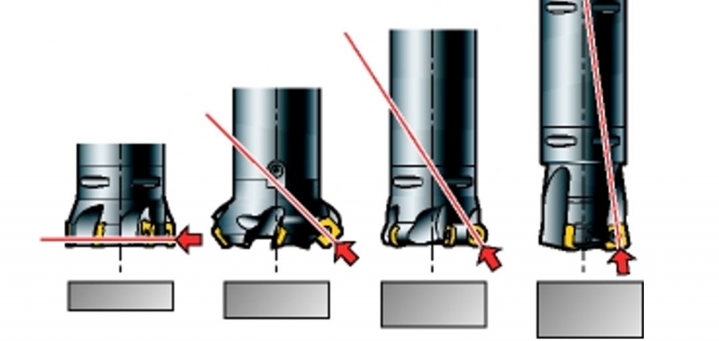
a) When using a 90° milling cutter, the cutting force is mainly concentrated in the radial direction. In long overhang conditions, this can cause the cutter to yaw; however, low axial forces are beneficial when milling thin-walled/vibration-sensitive parts.
b) The 45° milling cutter can generate evenly distributed axial and radial forces.
c) Round insert milling cutters direct most of the force up the spindle, especially when the depth of cut is small. In addition, the 10° cutter transmits the main cutting forces into the spindle, reducing vibration caused by long tool overhangs.

2) Choose the smallest possible diameter for the process.
3) DC should be 20-50% larger than AE.
4) Select sparse and/or unequal pitch milling cutters.
5) Lightweight milling cutters are advantageous, such as milling cutters with aluminum alloy bodies.
For unstable thin-walled workpieces, use a large entering angle = small axial cutting force; in the case of long tool overhang, use a small entering angle = high axial cutting force.
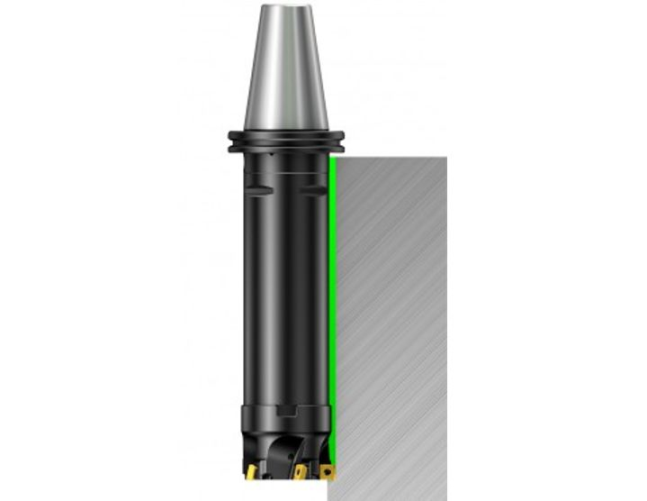
2. handle
Using the Coromant Capto® Modular Toolholder System it is possible to assemble tools of the required length while maintaining high stability and minimal run-out.
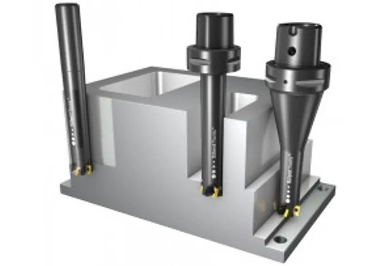
1) Keep the tool assembly as rigid and as short as possible.
2) Choose the largest possible post diameter/size.
3) Use Coromant Capto® adaptors for oversized cutters and avoid reducing adaptors.
4) For small size cutters, use tapered adaptors if possible.
5) In the process where the last pass is deep in the part, use the extended tool at the predetermined position. Adjust cutting parameters according to each tool length.
6) If the spindle speed exceeds 20,000 rpm, use a balanced cutting tool and an oversized milling cutter with a shank to be sure to use the shortest possible tool length, and gradually increase the length.(ALUMINUM BATTERY BOX ENCLOSURE)

3. Vibration reduction milling cutter
Milling vibration trends may become more pronounced if the overhang is greater than 4 times the tool diameter, and Silent Tools™ dampened milling cutters can significantly increase productivity.
4. Cutting edge
To reduce cutting forces:
1) Choose light duty geometry-L and thin coating grades with sharp cutting edges.
2) Use inserts with small nose radius and small parallel land.
Sometimes the tendency to vibrate can be reduced by adding more damping to the system. Use a larger cutting edge geometry with a negative rake and a slightly worn cutting edge.

5. Cutting parameters and toolpath programming
1) Always position the milling cutter off-center relative to the milling surface.
2) For KAPR 90° long-edge milling cutters or end mills, use a small radial depth of cut (max ae = 25% × DC) and a large axial depth of cut (max ap = 100% × De).
3) When face milling, use a small depth of cut ap and high feed fz and a round insert or a high feed milling cutter with a small entering angle.
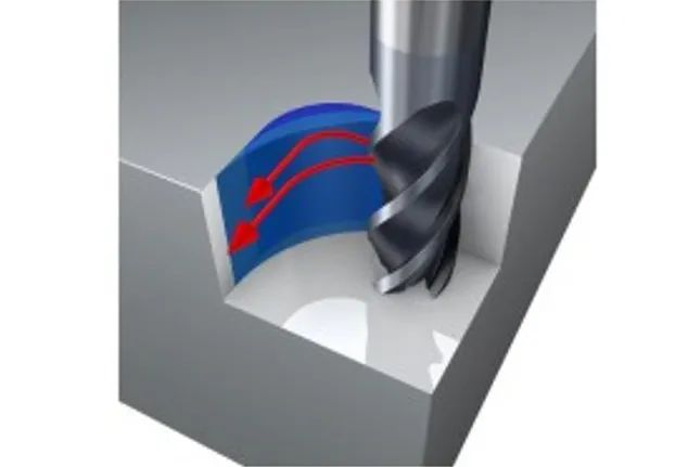
4) Avoid vibration in corners by programming a large arc pass, see milling inside corners .
5) If the chip thickness becomes too thin, the cutting edge will rub instead of cutting, causing vibration. In this case, the feed per tooth should be increased.
6. Machine tools
Machine condition can have a large influence on milling vibration trends. Excessive wear on the spindle bearings or feed mechanism will result in poor machining performance. Carefully choose machining strategies and cutting force directions to take full advantage of machine stability.
Every machine tool spindle has unstable areas prone to vibration. The stable cutting area is described by a stability graph and increases with increasing rotational speed. Even a speed increase as low as 50 rpm can change the cutting process from an unstable state of vibration to a stable state.(1590g Cnc Milled Box)
7. Workpiece and its fixture
When milling thin-walled/base-mounted parts and/or with less rigid fixtures, consider the following:
1) The fixture should be close to the machine table.
2) Optimize the toolpath and feed direction towards the location where the machine/fixture is strongest for the most stable cutting conditions .
3) Avoid machining in directions where the workpiece is not adequately supported.
4) When the fixture is And/or when the workpiece is less rigid in a particular direction, up-cut milling can reduce the tendency to vibrate.

When the rigidity is poor, use the feed direction toward the machine table.
Note that the first cut should be made at 1/2 the depth of cut of the second cut, the second cut should be made at 1/2 the depth of cut of the third cut, and so on.
